
Methods of extracting firmware from IoT devices – Part One
Overview
This is part one of a two part post about methods to extract firmware/Linux images from random IoT devices you may encounter.
This series of posts revolves around a device from Rainforest Automation, called the Eagle. The latest version is the Eagle-3 which is what we will be working with.
In part two we will deep dive into Linux device tree's, SPI flash, rebuilding OpenWrt and how vendors mishandle the GPL and its requirements.
If you want to get right into the technical details, skip ahead to the "Physical device" section.
If you want to understand why I wanted to use this device and what made me pull it apart, please read on.
Why the Eagle-3?
As part of my ongoing process to automate things in my home, I wanted to better understand my power usage. Australia now mandates the installation of level 4 smart meters or above. They are capable of reporting usage data. This data is reported via two networks, the Meter Local Area Network(MLAN) and Home Area Network(HAN). The Rainforest device is designed to communicate to the HAN via the Zigbee protocol. The MLAN is out of scope for this post.
I wanted a device that I could connect to my meter via the HAN and access usage data via a local API and I did not want to use a cloud service or some other 3rd party system.
Finding out about the Rainforest Eagle seemed like a good fit, but they also were pushing their cloud access solution.
I emailed them and they told me the Eagle can be used via a local API endpoint, much like their previous model could be. (The Eagle-200)
When I was reading this API guide, I saw a few references to a "Linux system" on the Eagle device. I had already decided to order the Eagle-3 by this point, as it was the only solution that really met my needs for a local API with documentation available.
However, the Linux side of it got me wondering, so I emailed them to ask about it.
The reply I got was:
The Linux System is internal to the device and is not available to the user.
Interesting reply…
GPL and Open source
A large part of my career and personal projects use Open Source software. I support and give back where and when I can. The GPL is an importation part of the Open Source movement, and I have a lot to thank for it existing.
However, Rainforest seem to be unaware of what the GPL means, they do include a small printed copy with the device.
I emailed Rainforest with some questions around their usage of GPL licensed components.
Given we know the device runs Linux and must have some GPL software given the inclusion of the printed license.
A few emails of back and forth, and I was told I can download the source code from:
http://downloads.openwrt.org/chaos_calmer/15.05.1/.
Not what I was expecting, I would have expected links to source code that runs on the device, not a link to the upstream operating system's source code.
However, now we know it runs OpenWrt.
Knowing it runs OpenWrt and that project is also licenses as GPL-v2, I emailed them again.
This time I sent along some supporting links about how to comply with the GPL.
The reply I got was:
This e-mail is written to confirm we used exact code, Rainforest Automation Inc. did not modify Linux code.
Fascinating!
So somehow a vanilla OpenWrt device can talk to my smart meter?
Using unmodified code, let's find out!
Physical device
When I finally got my Eagle-3, I connected to the local IP address it was assigned via DHCP.
Nothing fascinating here, a few pages to set up the device but not a lot and most definitely not OpenWrt LuCI interface but rather a very custom/cut down configuration page for the device.
All a bit dull, so the next step for me is to open the device and see what we can find.
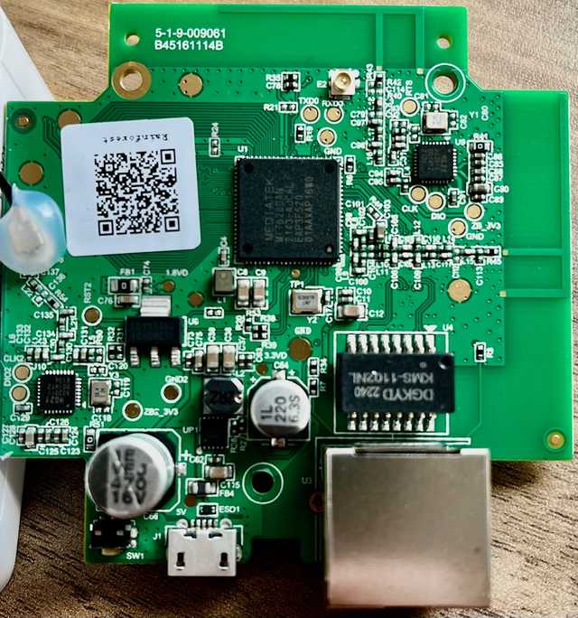
On the top side of the PCB I can see the SOC MT7628AN and a few other chips.
I also spot what I assume is the MIPS EJTAG interface test access points (TAP)
CLK, RTS, DIO etc...
OpenOCD has more information about how to access these test points.
This topic it is out of scope for this post.
However, I do spot some pads labelled TXD0, RXD0 and GND that very much looks like a UART port to me!
The bottom side of the PCB is less interesting.
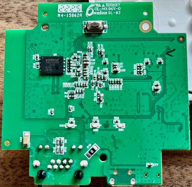
I do spot the SPI flash chip, it is a W25Q512JV.
This is a 512M-bit Serial Flash Memory in a WSON8 package.
The rest of the chips are of little interest for now.
UART Access
Lets see if that UART is doing anything.
Solder some wires or headers to the pads labelled TXD0, RXD0 and GND.
After a bit of trial and error I discover the port settings are 57600,8,n,1.
Power on the device and what do we see!
I can see it runs U-boot:
[04010D0B][04010D08]
DDR Calibration DQS reg = 0000888A

U-Boot 1.1.3 (Nov 22 2022 - 14:10:02)

Board: Ralink APSoC DRAM:  64 MB
relocate_code Pointer at: 83f9c000
flash manufacture id: ef, device id 40 20
find flash: W25Q512JV
============================================
Ralink UBoot Version: 5.0.0.0
--------------------------------------------
ASIC 7628_MP (Port5<->None)
DRAM component: 512 Mbits DDR, width 16
DRAM bus: 16 bit
Total memory: 64 MBytes
Flash component: SPI Flash
Date:Nov 22 2022  Time:14:10:02
============================================
icache: sets:512, ways:4, linesz:32 ,total:65536
dcache: sets:256, ways:4, linesz:32 ,total:32768

 ##### The CPU freq = 580 MHZ ####
 estimate memory size =64 Mbytes
RESET MT7628 PHY!!!!!!wps val:4
Detect WPS Button!
wps val:4
default: 3

Please choose the operation:
   1: Load system code to SDRAM via TFTP.
   2: Load system code then write to Flash via TFTP.
   3: Boot system code via Flash (default).
   4: Entr boot command line interface.
   7: Load Boot Loader code then write to Flash via Serial.
   9: Load Boot Loader code then write to Flash via TFTP.
 0

3: System Boot system code via Flash.
Okay, so it runs U-boot and boots into Linux, as expected.
## Booting image at bc050000 ...
   Image Name:   MIPS OpenWrt Linux-4.14.267
   Image Type:   MIPS Linux Kernel Image (lzma compressed)
   Data Size:    1707552 Bytes =  1.6 MB
   Load Address: 80000000
   Entry Point:  80000000
   Verifying Checksum ... OK
   Uncompressing Kernel Image ... OK
No initrd
## Transferring control to Linux (at address 80000000) ...
## Giving linux memsize in MB, 64

Starting kernel ...

[0.000000] Linux version 4.14.267 (jmarcellin@vanbld14) (gcc version 7.5.0 (OpenWrt GCC 7.5.0 r11405-2a3552))- The above boot output has been truncated to only show the first line of Linux booting. Download the boot-log/dmesg.
Once it's booted, you are greeted with a Linux shell login. I tried a few generic passwords but no luck.
However now I am determined to get access to a root shell…
U-boot
Since we can not log in via the shell, let's take a look at what we can do via U-boot.
OpenWrt and kernel CMDLINE
By default, OpenWrt is set to ignore CMDLINE options passed to it via u-boot.
This ensures no weird OEM/manufacture configured settings in u-boot will affect OpenWrt when booting images.
Makes sense, however it now means we can not make use of bootargs or bootcmd to manipulate the running kernel or settings passed to the kernel. This prevents us from setting init= to some binary that we can use to bypass the login shell.
Okay, so another option/method we can not make use of, there are still plenty more options we can try.
OpenWrt Recovery mode
If you have done much with OpenWrt, you will know when it boots you get the option of entering a recovery console/mode on the serial console.
It looks similar to this:
Press the [f] key and hit [enter] to enter failsafe modeHowever, if you look at when the Eagle booted we did not see this option, you see some references to debug levels but nothing about entering a recovery mode.
OpenWrt build system has an option called: TARGET_PREINIT_DISABLE_FAILSAFE if this is set to y then the build system will remove support for the recovery mode.
This is a clear difference from upstream OpenWrt as they always leave recovery mode enabled. Rainforest has enabled this build time setting to prevent recovery mode access as it will bypass the root shell login requirement.
Another option we can't make use of…
Dumping the flash
So we can't log in via the shell, we can't edit u-boot and there is no OpenWrt recovery mode.
Seems like it's time to just dump the flash and analyse it via binwalk offline.
Let's take a look at how we can do that next.
Dumping flash via U-boot
U-boot provides a sf command-set to manipulate SPI flash storage.
You can erase, read and write to and from the SPI flash. Most importantly, you can read the contents of the flash into memory.
U-boot also provides a md command to dump the contents of the device memory to the running terminal, useful to check sections of memory and their values.
So if you set up a log file in Minicom, then read the SPI flash into memory via sf read ... then dump it to the console via the md.b (use Binary mode to display) command you will have a full dump of the flash saved in your log file. It will need some manipulation, but all the data will be present.
Example using the md command to dump 0x10 (16) bytes, starting from address 0x0:
MT7628 # help md
md [.b, .w, .l] address [# of objects]
    - memory display
MT7628 # md.b 0x0 0x10
00000000: 01 00 00 a0 02 00 00 a0 03 00 00 a0 04 00 00 a0    ................
MT7628 #
Yes, it is slow, but it is a simple and safe way to dump the flash.
Taking a look at the options we have in U-boot:
MT7628 # help
?       - alias for 'help'
bootm   - boot application image from memory
cp      - memory copy
erase   - erase SPI FLASH memory
go      - start application at address 'addr'
help    - print online help
loadb   - load binary file over serial line (kermit mode)
md      - memory display
mdio   - Ralink PHY register R/W command !!
mm      - memory modify (auto-incrementing)
nm      - memory modify (constant address)
printenv- print environment variables
reset   - Perform RESET of the CPU
rf      - read/write rf register
saveenv - save environment variables to persistent storage
setenv  - set environment variables
spi     - spi command
tftpboot- boot image via network using TFTP protocol
version - print monitor version
MT7628 #
As we can see the vendor that compiled u-boot for this device has removed the sf command-set.
The spi command-set is not the same as you can not read into memory in the same manner as the sf command, nor can you probe/initialise the flash.
Okay, so add that to the list of things we can't do.
Dumping via a generic OpenWrt image
NOTE: Setting up a TFTP server/environment is out of scope in this post.
OpenWrt provides a generic image for this CPU and board, mt76x8-mediatek_mt7628an-eval-board maybe we can try boot that.
Since we are not interested in installing OpenWrt, we make use of the initramfs images provided by OpenWrt, as that will give us a live shell environment we can work in.
Using printenv you can see what filename the TFTP command will try to fetch, in our case it is test.bin. Move the image you downloaded previously and rename it test.bin in the TFTP servers directory. You could also update the environment variables in u-boot.
Let's try to boot the OpenWrt image.
First download the image to the device:
MT7628 # tftpboot

 NetLoop,call eth_halt !

 NetLoop,call eth_init !
Trying Eth0 (10/100-M)

 Waitting for RX_DMA_BUSY status Start... done


 ETH_STATE_ACTIVE!!
TFTP from server 192.168.0.120; our IP address is 192.168.0.3
Filename 'test.bin'.

 TIMEOUT_COUNT=10,Load address: 0x82000000
Loading: Got ARP REPLY, set server/gtwy eth addr (34:13:e8:c6:39:a0)
Got it
#################################################################
         #################################################################
         #################################################################
         ##############################Got ARP REQUEST, return our IP
         #################################################################
         #################################################################
         #################################################################
         #################################################################
         #################################################################
         #################################################################
         #################################################################
         #################################################################
         #################################################################
         #################################################################
         #################################################################
         #################################################################
         #################################################################
         ###
done
Bytes transferred = 5670546 (568692 hex)
LoadAddr=82000000 NetBootFileXferSize= 00568692
MT7628 #
NOTE: If you have autostart=yes set the device will boot the image right away, I have disabled it via thesetenv command, so we need to manually boot the image.
Boot the image at the address 82000000:
## Booting image at 82000000 ...
   Image Name:   MIPS OpenWrt Linux-5.15.134
   Image Type:   MIPS Linux Kernel Image (lzma compressed)
   Data Size:    5670482 Bytes =  5.4 MB
   Load Address: 80000000
   Entry Point:  80000000
   Verifying Checksum ... OK
   Uncompressing Kernel Image ... OK
No initrd
## Transferring control to Linux (at address 80000000) ...
## Giving linux memsize in MB, 64

Starting kernel ...

[0.000000] Linux version 5.15.134 (builder@buildhost) (mipsel-openwrt-linux-musl-gcc (OpenWrt GCC 12.3.0 r23497-6637af95aa)
NOTE: The above boot output has been truncated.
Mounting mtd partitions
However, it fails to correct identify all the partitions on the flash.
Looking at the output of cat /proc/mtd we can see that the rootfs_data anddata partitions are missing when we boot via the generic initramfs image:
root@OpenWrt:/# cat /proc/mtd
dev:    size   erasesize  name
mtd0: 00030000 00010000 "u-boot"
mtd1: 00010000 00010000 "u-boot-env"
mtd2: 00010000 00010000 "factory"
mtd3: 007b0000 00010000 "firmware"
mtd4: 001a0e60 00010000 "kernel"
mtd5: 0060f1a0 00010000 "rootfs"
root@OpenWrt:/#
Inspecting the output of dmesg we can see the address of the partitions are incorrect as well.
For example, the rootfs partition in the Eagle dmesg output is:
0x0000001a0e60-0x000001bb0000 : "rootfs"and the OpenWrt dmesg is:
0x0000001a0e60-0x0000007b0000 : "rootfs"Given the above two issues we can not mount the file-system, so we will not be able change the root password or do anything else.
We can not dump the individual mtd partitions as the addresses are incorrect, so we would end up with garbage / invalid data if we tried to dump them.
For reference, this is what the partitions and their offsets look like when the Eagle boots with the firmware from Rainforest:
[    0.627999] 0x000000000000-0x000000030000 : "u-boot"
[    0.638758] 0x000000030000-0x000000040000 : "u-boot-env"
[    0.650192] 0x000000040000-0x000000050000 : "factory"
[    0.661129] 0x000000050000-0x000001c00000 : "firmware"
[    0.674865] 2 uimage-fw partitions found on MTD device firmware
[    0.686659] Creating 2 MTD partitions on "firmware":
[    0.696510] 0x000000000000-0x0000001a0e60 : "kernel"
[    0.707264] 0x0000001a0e60-0x000001bb0000 : "rootfs"
[    0.717979] mtd: device 5 (rootfs) set to be root filesystem
[    0.730686] 1 squashfs-split partitions found on MTD device rootfs
[    0.742999] 0x0000013e0000-0x000001bb0000 : "rootfs_data"
[    0.754627] 0x000001c00000-0x000004000000 : "data"
Okay, So that rules out the generic OpenWrt image for now.
Access the raw flash chip via SPI
Is it possible to use flashrom and dump the flash connected to the SPI bus?
Sadly, there are no /dev/spi*devices present, so even if flashrom supported this device, there simply is no way to access the raw SPI device nodes.
root@OpenWrt:/# ls -la /dev/sp*
ls: /dev/sp*: No such file or directory
root@OpenWrt:/#
That makes sense when we look at the OpenWrt device tree for the generic image, there are no spidev compatible devices listed.
Installing the OpenWrt package kmod-spi-dev itself will not help, as our flash device is not present in the kernel source in spidev.c. Thus, the SPI device needs to be defined in the device tree so that the kernel knows where to physically locate the SPI device.
Failed methods so far…
So far, the following methods have failed:
- Overriding the Linux init process via cmdline arguments
- U-boot via sf/md tools to dump the flash
- OpenWrt recovery mode
- OpenWrt and dumping the mtd partitions
- OpenWrt to access the flash via SPI
That leaves us with dumping the flash via external tools and devices.
Or we keep digging…
Given we know the offsets for the correct mtd partitions, we have some other options before we consider attaching an external device to dump the flash.
Part one summary
We have now exhausted all the common methods used to dump flash images.
External readers are a possibility, but they do not come without risks of their own. You might fry the chip, you might need to remove it from the board, there are a bunch of things that might go wrong.
With that in mind, I am not going to make use of external methods just yet.
However, we do know Linux supports the W25Q512JV flash chip, and we have the raw offsets of each mtd partition from the original boot-log…
We should be able to get this working via a simple device tree definition.
In part two we will continue down the path of exploring the device tree and with some luck finally get a root shell on the device.
References and further reading
A list of supporting documents, data sheets, references and related further reading.
- Smart meter connectivity levels explained
- Smart Grid Metering Networks: A Survey on Security, Privacy and Open Research Issues
- Rainforest local API manual
- MIPS EJTAG Specification, revision 6.10
- OpenOCD JTAG Primer
- U-boot reference to OpenWrt ignoring bootargs
- OpenWrt reference to ignoring bootargs
- U-boot manual on environment variables
- U-boot manual on the sf command
- OpenWrt-Devel: Allow to disable failsafe mode patch
- OpenWrt mt76x8 images
- How to dump flash via serial and u-boot md command
- OpenIPC dump flash via serial and convert to .bin